
OPNsense 26.1 Setup Guide: The Ultimate Homelab Firewall 2026 (Part 1)
The OPNsense Architect
Welcome to the first real step in my recommended Ultimate Homelab Security Guide. If your network is the castle, your firewall is the main gate, the high walls, and the guard towers all in one. We're not going to use the flimsy consumer-grade or ISP provided junk. Prepare to build a fortress with OPNsense.
OPNsense is an open-source, enterprise-grade firewall and routing platform based on FreeBSD. It's the "pro" in "prosumer" and the perfect brain for your secure homelab network. I've been using OPNsense since 2017 through all the various iterations from that time, to now. While not perfect, it ticks a LOT of boxes and double-taps some of them!
This guide will walk you through the entire process, step-by-step, from a bare-metal machine to a functioning, secure-by-default firewall. This is the foundation we will build all future security upon - VLANs, Intrusion Detection (Suricata), Application Filtering (Zenarmor), and more. You can run OPNsense on a physical computer or as a virtual machine, but I very strongly recommend running it on it's own hardware, which is what this guide will focus on. When I originally started with OPN, it was as a VM on an ancient Dell tower dual socket Xeon server that I was running all kinds of stuff on. Once I switched it to dedicated hardware, I never looked back. Something about the OS living right on the bare-metal and the instant snappiness. This is the old-school nerd in me coming out...
OPNsense operates at almost every layer of the OSI model, here's what I mean:
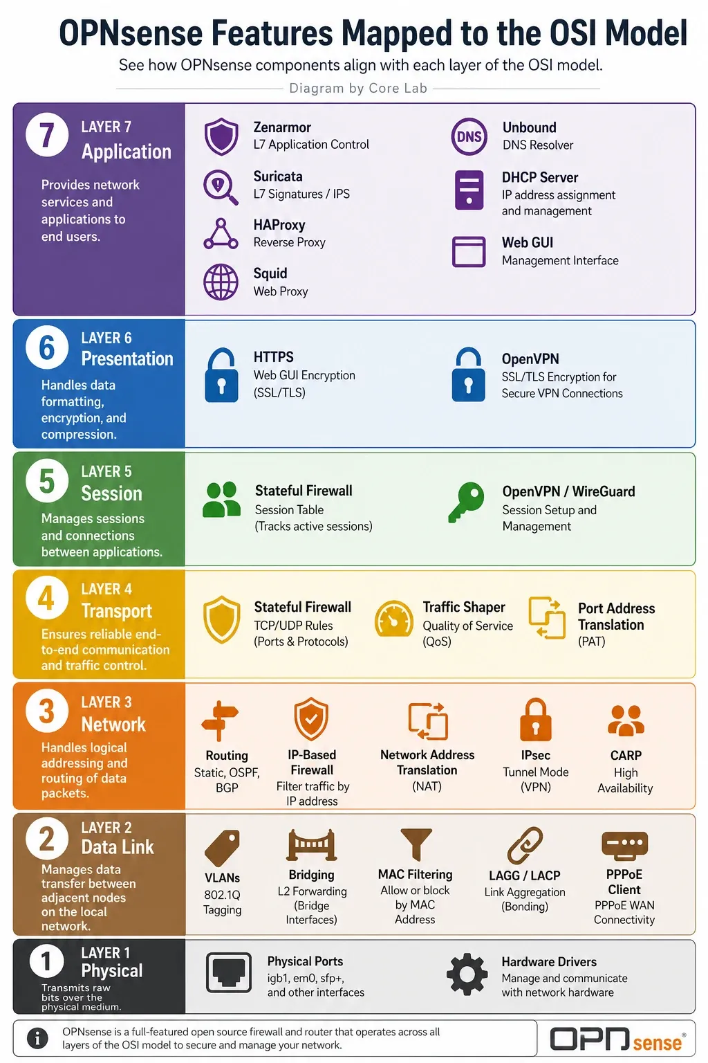
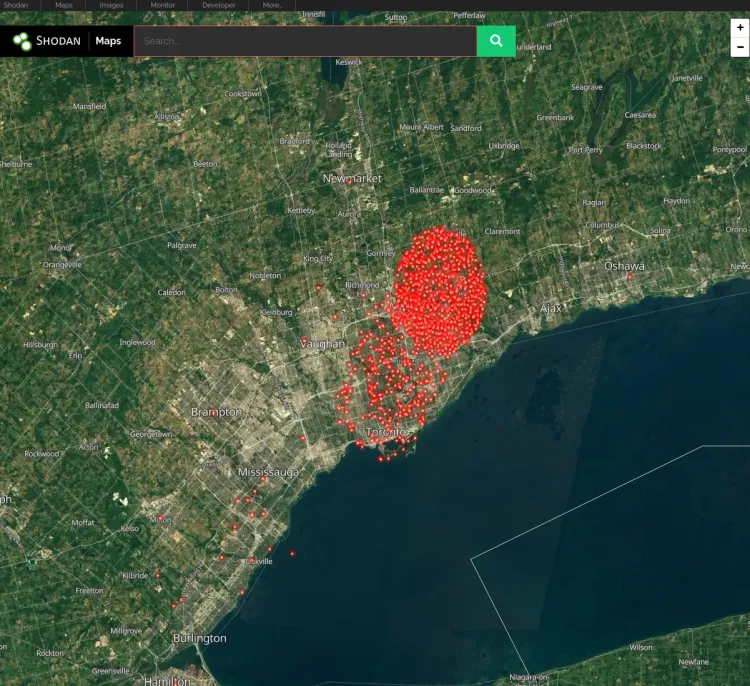
When you're done implementing this guide, your network will be protected from Shodan scanners, Bogons, known Botnets, Malware sites, and more.
Let's get to work.
OPNsense Version 26.1.x Key Changes📒
- The "Kea/DNSMasq vs. ISC" Fork: In 26.1, the legacy ISC DHCP daemon is officially deprecated (moved to a plugin).The New Defaults: Choose DNSMasq or Kea DHCP as your new DNS for new installs. I chose DNSMasq as it can do both DNS & DHCP and is recommended by OPN for smaller (Home) deployments.The Warning: Kea does not natively register dynamic hostnames in Unbound DNS yet (only static ones). If you use Kea and rely on
device-name.home.arpaworking automatically, you will need to install theos-isc-dhcpplugin or use the communityos-kea-unboundscript. - Terminology Update (NAT): The "Port Forward" menu has been renamed/migrated to "Destination NAT" in the new version.The New Location: "Firewall -> NAT -> Port Forward" to "Firewall -> NAT -> Destination NAT."
- IPv6 "Identity Association": 26.1 introduced a new IPv6 mode.The Fix: Many homelabbers struggle with "Track Interface." Identity Association is the new preferred way to handle prefix delegation for modern ISP setups that utilize IPV6.
Hardware Selection: Building Your "Scrap Lab" Fortress
Before we start, you'll need:
- A Dedicated Machine: A PC, server, mini-PC or appliance with at least two Network Interfaces. One for your "WAN" (Internet in) and one for your "LAN" (Internal network out). Regardless if this is two separate NICs or just multiple RJ45 ports on the same NIC, you need two!
- Not critical any longer but still greatly preferred, any Intel based NIC. WHY: OPNsense is based off of FreeBSD and uses it's drivers for compatibility, of which Intel works extremely well. Newer Intel NICs utilize the igb driver which is a "polling" based NIC vs the older "interrupt" style, so on higher throughput operations, polling based igb does better at utilizing multi-core processors.
- The OPNsense Image: Download the latest
vgaimage from the OPNsense website. - A USB Stick: At least 4GB. You'll use a tool like Rufus or balenaEtcher to flash the image.
- Patience: This is a powerful tool. Read twice, execute once.
Incredible Mini-PC for OPNsense - GMKtec M8 Mini-PC!
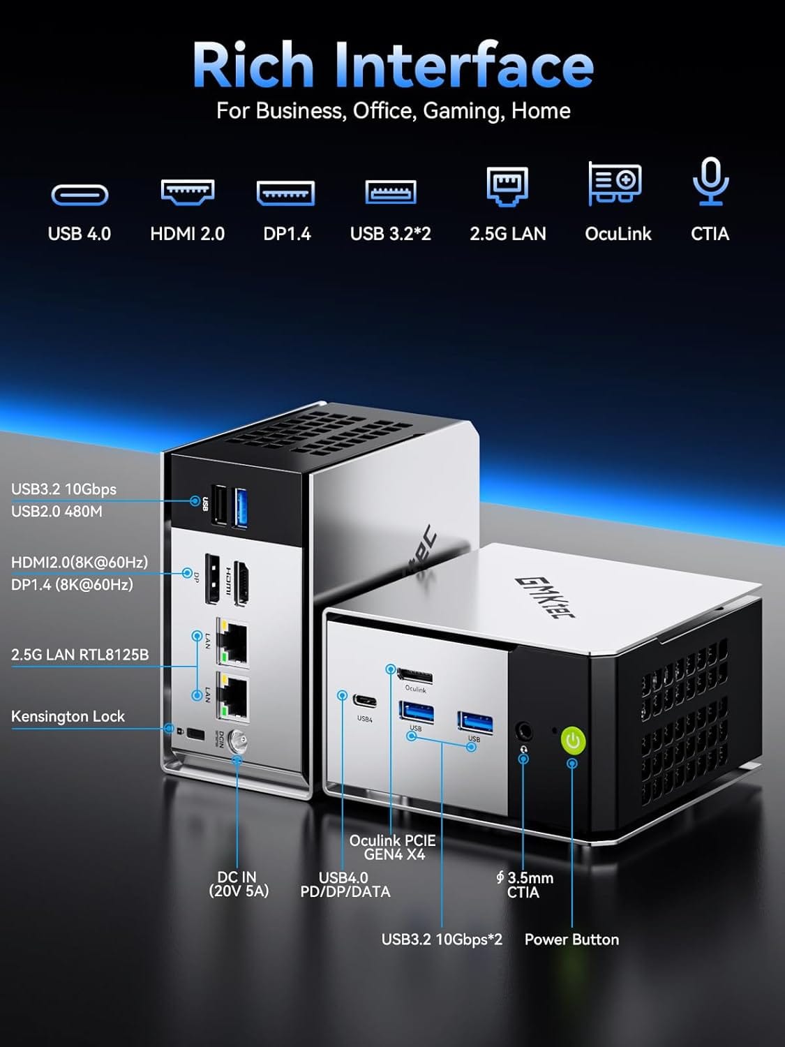
GMKtec Mini PC M8 Desktop Computer
- AMD Ryzen PRO 6650H (6C/12T 4.50Ghz)
- Dual NIC LAN 2.5GbE
- 16GB LPDDR5 RAM
- 512GB Hard Drive PCle SSD
- Oculink, USB4, HDMI, USB-C
Part 1: Bare Metal Installation & ZFS Configuration
Installing OPNsense onto bare metal is a streamlined process, but it requires navigating a critical transition from a temporary live environment into the actual persistent system installer.
1. Flash the Installation Image
Download the appropriate official OPNsense image (VGA or Serial depending on your motherboard console requirements). Before writing the image to your media, make sure to decompress the archive:
# On Unix-like systems, decompress the bzip2 payload before using dd
bunzip2 OPNsense-XX.X.XX-vga-amd64.img.bz2
Use a raw block-writing tool like Rufus (in DD Mode), BalenaEtcher, or standard terminal dd to write the uncompressed .img file directly to an empty USB storage drive. Don't overthink this part, you won't break anything and you can use almost any tool.
2. Live Boot and the Installation Console
Plug your installation USB drive into the target firewall hardware, attach a local display and keyboard, and configure your system BIOS/UEFI to override the standard boot path to execute from the USB media.
Once the FreeBSD kernel finishes loading, the platform loads completely as a Live System and prompts you with a standard login console banner.
To initialize the persistent setup script, you have two distinct options at the prompt:
- Option A (Direct Path): Log in directly using the installer identity.
- User: installer
- Password: opnsense
- Option B (Root Escalation Path): If you initially logged into the root system account (root / opnsense) to audit hardware parameters or view system logs from the live image shell, you must explicitly drop out of the live terminal and switch to the installer script context by running:
su - installerExecuting either option instantly terminates the raw shell environment and launches the interactive Text-User Interface (TUI) installer wizard.
Part 2: Navigating the TUI Installer Wizard
Step 1: Configure Local Keymap
Select your preferred keyboard mapping scheme (e.g., US Standard or your specific regional layout) from the menu. Confirm the selection to proceed.
Step 2: Select File System Architecture (ZFS)
When prompted with the installation type, choose Install (ZFS). Since native ZFS integration became standard, it is the recommended filesystem for production firewall deployments. I've been using it since the second it was available, having already been an early-homelab adopter of ZFS since roughly 2013!
Even on a single disk topology, selecting ZFS gives your network edge enterprise-grade block protection, Adaptive Replacement Cache (ARC) for ultra-fast rule lookups, and native system Snapshots. This allows you to generate a localized system snapshot immediately prior to running major system upgrades - if a package updates cleanly but breaks a custom plugin, you can roll back your system state instantaneously.
Step 3: Define Virtual Device Topology (ZFS Partitioning)
Select your target drive layout. For single-drive installations, select Stripe as the device type. If your hardware contains redundant disks, choose your mirrored layout here.
Step 4: Target Disk Selection
Identify and highlight the internal target drive where OPNsense will permanently reside (e.g., ada0 for legacy SATA or nvd0 for NVMe devices).
Step 5: Destructive Commitment & Flash Operation
The wizard will present a final Last Chance! warning alerting you that proceeding will completely wipe the target disk payload. Confirm Yes to format the drive and begin unpacking the base firewall binaries onto your local storage.
Step 6: Hardening the Console Account
As the installer wraps up, it will explicitly prompt you to modify the default Root Password. Provide a complex, cryptographically strong passphrase. This credential governs direct physical console access, serial communication, and SSH administration. If all else fails, this is the last bastion of security for your firewall! At password of at least 16 characters is recommended, with plenty of entropy.
Step 7: Final Polish and System Reboot
Select Complete Install to close out the execution wizard. As the machine cycles down to restart, physically eject the installation USB drive from the hardware chassis. This prevents the system loop from booting straight back into the live installer environment.
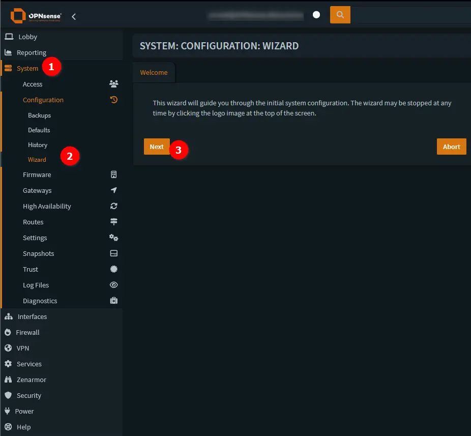
Part 3: The Initial Setup Wizard & The New DHCP Reality
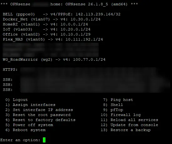
On its first boot, OPNsense will stop and ask you to assign your network interfaces. This is the most critical setup step and it's useful, especially if you're new to OPNsense.
Assign Interfaces:
- OPNsense will list the NICs it has detected (e.g.,
em0,em1). - OPNsense generally tries to autodetect which is the WAN and LAN ports, but if that fails or is incorrect, you can pick.
- It will ask you to identify your WAN (Internet) interface first. Plug the cable from your modem into the port you want to be your WAN, and OPNsense should detect the "link up" status. Type the name of that interface (e.g.,
em0) and press Enter. - It will then ask you to identify your LAN interface. Plug a cable from your switch or your computer into the port you want to be your LAN. Type its name (e.g.,
em1) and press Enter. - It may ask for optional interfaces (OPT1, OPT2...). Just press Enter to skip this for now.
- Confirm the assignments. OPNsense will now finish booting.
- Connect to the Web GUI:
- Your computer, connected to the LAN port, should now get an IP address via DHCP from OPNsense.
- By default, OPNsense is available at
http://192.168.1.1. - Open your browser and navigate to that address. You may get an SSL warning; proceed anyway.
- Log in with the username
rootand the password you set during installation.
- Run the Setup Wizard: The wizard will start automatically.
- Hostname/Domain: Give it a name, e.g.,
opnsense.corelab.tech. Mine is actually named to an internal private network ;)
Configuring Trusted DNS (Cloudflare & CIRA)
- DNS Servers: Set these to trusted resolvers. I recommend Cloudflare(
1.1.1.1,1.0.0.1) or Quad9(9.9.9.9,149.112.112.112). Uncheck the "Allow DNS override" box for the WAN. - Timezone: Set your correct timezone.
- Configure WAN: For most home users, this will be DHCP. If you have a static IP from your ISP, enter it here. Crucially: Scroll to the bottom and uncheck "Block RFC1918 Private Networks" and "Block Bogon Networks." While this sounds counter-intuitive, many ISPs use private IPs in their network, and this can cause issues. If your ISP modem/router is already in bridge or bypass mode, you can leave these enabled. Regardless, we'll set up better rules later.
- Normal ISP connection, generally DHCP + leave the two checkboxes enabled.
- PPPoE ISP - Slightly more complex setup, guide to be added later.
- Normal ISP but CG-NAT / Double-Nat-ed - Uncheck the RFC1918 & Bogon rules.
🍁 A Note fellow Canadians: CIRA Canadian Shield
If you're in Canada, you have a fantastic, high-performance, and privacy-focused DNS option available from the Canadian Internet Registration Authority (CIRA) - the same non-profit that manages the .CA domain.
Unlike some other resolvers, CIRA's servers are all located exclusively in Canada, meaning your DNS queries are resolved on Canadian soil and are protected by Canadian privacy laws. They offer three free tiers of service; just pick the one that's right for you.
Here are the DNS servers you can use:
CIRA Canadian Shield DNS Servers
1. Private
This is a fast, private DNS resolver. It does not block anything and is purely for DNS resolution.
- IPv4:
149.112.121.10&149.112.122.10 - IPv6:
2620:10A:80BB::10&2620:10A:80BC::10
2. Protected
This is the one I recommend for most users. It includes all the speed and privacy of the "Private" tier but also blocks access to known malicious domains, protecting you from malware, botnets, and phishing attacks.
- IPv4:
149.112.121.20&149.112.122.20 - IPv6:
2620:10A:80BB::20&2620:10A:80BC::20
3. Family
This tier includes all the protection from the "Protected" level (blocking malware and phishing) but also blocks access to pornographic and sexually explicit content. This is a great "set it and forget it" option for households with kids.
- IPv4:
149.112.121.30&149.112.122.30 - IPv6:
2620:10A:80BB::30&2620:10A:80BC::30
Migration Alert: Moving from ISC DHCP to Dnsmasq or Kea
LAN & IP Address Best Practices
- Configure LAN: Change this immediately! You don't want to use the default
192.168.1.1as it can conflict with other routers. Peasants use defaults! You're not a peasant if you're going to run your own firewall 😏- I use a
10.x.x.xscheme. Let's set it to10.10.1.1with a subnet mask of/24. Ensure the DHCP range is updated to match (e.g.,10.10.1.100to10.10.1.200).
- I use a
- Admin Password: Change your
rootuser's Web GUI password. Do not re-use your console password. - Reload: The wizard will apply your settings. You will be disconnected and will need to browse to your new LAN IP (e.g.,
http://10.10.1.1).
Part 4: Network Segmentation & VLAN Architecture
Your firewall is running, it's already blocking everything inbound by default. Let's step this up a notch... Enforce a digital "moat". We do this by subscribing to IP blocklists using Aliases. An Alias is just a dynamic list of IPs that OPNsense can automatically update.
The Plan: Our Network Design
We will create the following VLANs. The IP scheme is a common pro-sumer setup: 10.10.X.1, where X is the VLAN ID number.
| VLAN Name | Tag ID | Subnet | Purpose |
| LAN | (Native) | 10.10.1.1/24 | Trusted Devices (Your PC, Phone) |
| MANAGEMENT | 10 | 10.10.10.1/24 | IPMI, Proxmox Admin, Switches |
| GUEST | 20 | 10.10.20.1/24 | Visitors (Internet Only) |
| IOT | 30 | 10.10.30.1/24 | Smart Bulbs, Fridges (Internet Only) |
| CAMERAS | 40 | 10.10.40.1/24 | Security Cams (No Internet) |
| DMZ | 50 | 10.10.50.1/24 | Public facing servers |
Prerequisites
This guide assumes you have one piece of essential hardware: a VLAN-capable Managed Switch. A basic, unmanaged "dumb" switch cannot handle the VLAN tags we'll be creating. Popular brands include Ubiquiti UniFi, TP-Link Omada, Netgear, and Mikrotik.
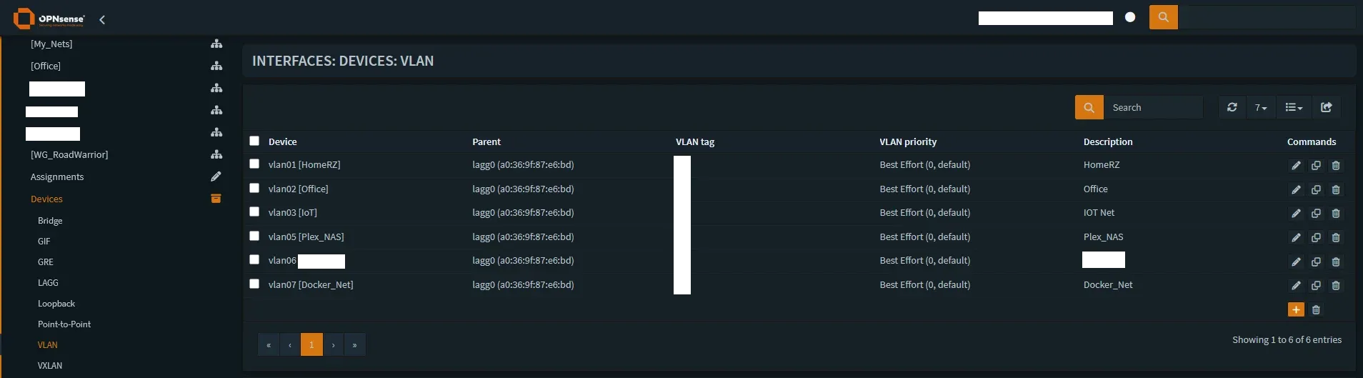
Step 4.1: Create the VLANs
- Navigate to Interfaces -> Other Types -> VLAN.
- Click the + (Add) button.
- Parent: Select your primary LAN interface (e.g.,
em1origb1). - VLAN Tag:
10 - Description:
MANAGEMENT - Click Save.
- Repeat for VLANs 20, 30, 40, 50.
Step 4.2: Assign VLANs to New Interfaces
- Navigate to Interfaces -> Assignments.
- In the dropdown at the bottom, select a new VLAN (e.g.,
VLAN 10) and click +. - It will appear as
OPT1. Click onOPT1to edit it. - Enable Interface: Checked.
- Description: Rename to
MANAGEMENT. - IPv4 Configuration Type: Static IPv4.
- IPv4 Address:
10.10.10.1and select/24from the dropdown. - Click Save.
- Repeat for all other VLANs.
Step 4.3: Configure DHCP for Each VLAN
In the v25.x days, we used the old ISC DHCP service. As of OPNsense 26.1, Dnsmasq or Kea are the choices you have for DHCP, DNS and Router Advertisement (RA) provider. While you can install the ISC plugin for nostalgia, I recommend moving to the modern stack which is what I did immediately.
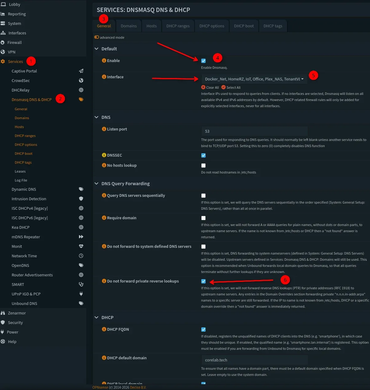
- Navigate to:
Services -> Dnsmasq DNS & DHCP -> General. - Enable DHCP: Ensure "Enable Dnsmasq" is checked. Dnsmasq now handles both your DNS resolution and your DHCP leases in a unified interface. I chose to use Dnsmaq for both at Core Lab.
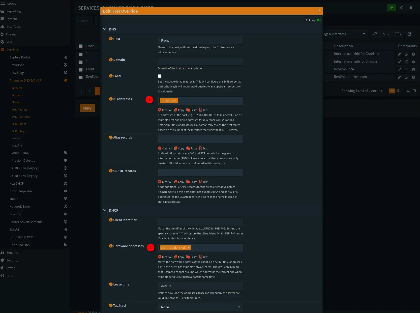
- Hit the Hosts tab and enter any static hosts you want to keep here, but you must have their MAC addresses as shown below 👇
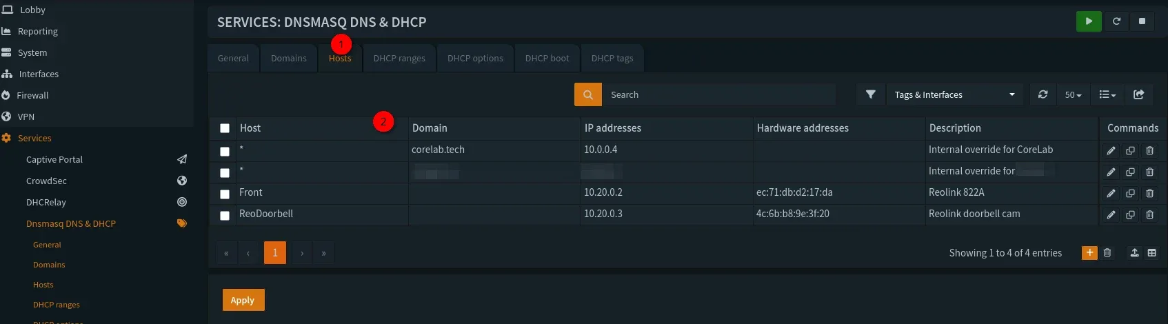
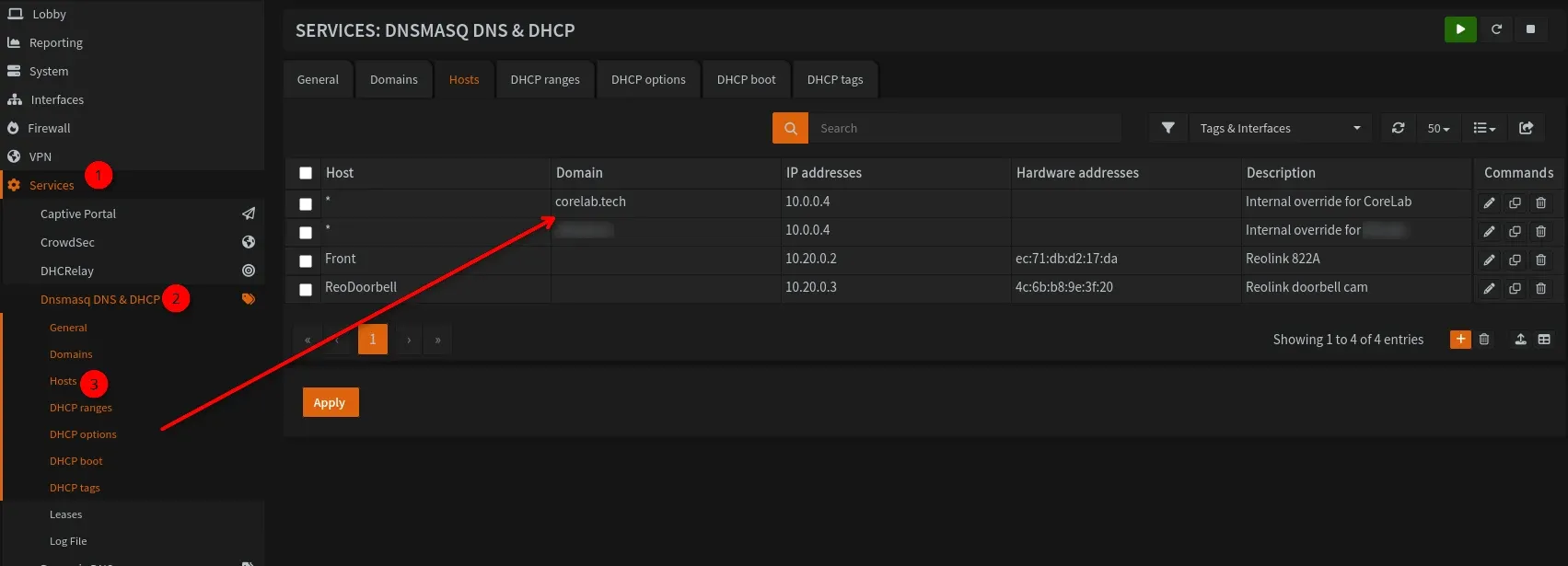
- This is also where you'd put in a DNS re-write if you want to access something internal like, your own website or an Aarr app being served by your reverse proxy. For me, I have a wildcard entry so that every time I try to reach
corelab.techfrom inside my own LAN, it's sent to my reverse proxy! You use a * in the host,domain.namein the Domain field, and the IP address pointed at your reverse proxy. 👨🍳
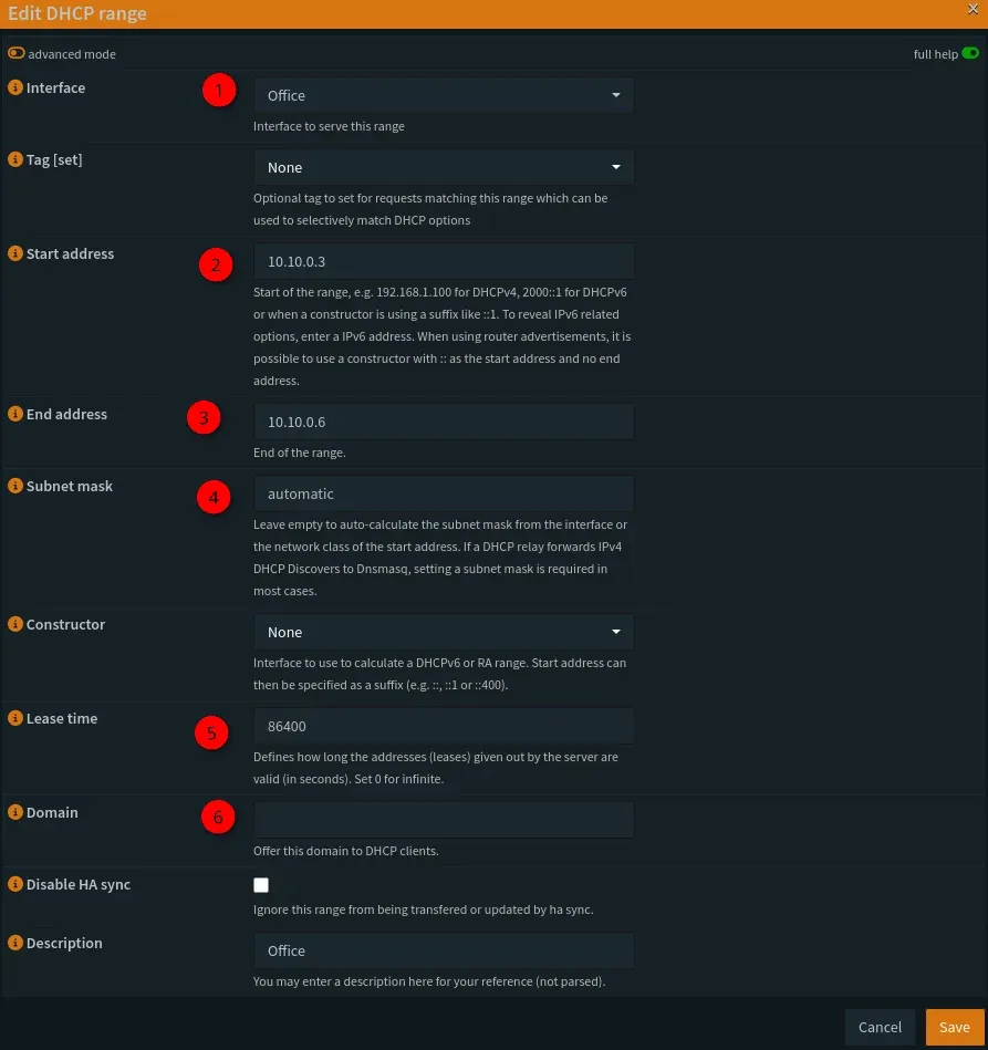
- Next up, and important ❗- Set your DHCP ranges for each interface (vlan!)
- This should match the subnet you assigned for each interface, in other words if your internal home LAN was /24 (255.255.255.0) you would ensure the net mask stays the same. You can start your DHCP range at 10 or 20 addresses in, if you want to keep some saved for static assignments etc...

- Alternative (The Pro Path): If you want the new enterprise standard, navigate to
Services -> Kea -> DHCPv4. Click the [+] to add a subnet.- Subnet:
10.10.10.0/24 - Pool:
10.10.10.100 - 10.10.10.200 - Why Kea? It’s built on the new MVC/API framework, making it faster and more stable for high-automation environments.
- Subnet:
Step 4.4: Configuring the "Router on a Stick" Trunk Port
A "router on a stick" is a very common and efficient configuration where a single physical interface on your OPNsense firewall (like its only RJ45 port) is used to manage and route traffic for multiple, isolated VLANs.
Instead of needing a separate physical port for your LAN, IoT, and Guest networks, you create virtual sub-interfaces on that single OPNsense port, one for each VLAN tag (e.g., 10, 20, 30). This port is then connected via a single cable to a "trunk" port on your managed switch. The switch handles tagging traffic from your end devices (like a camera on VLAN 40) before sending it "up the stick" to OPNsense. OPNsense applies your firewall rules to this tagged traffic - blocking or allowing it—and then sends it right back down the same cable to the switch to be routed to its final destination, whether that's another VLAN or out to the internet.
- You can set up a LAGG under Interfaces->Devices->LAGG
- Step 1: Hit the + to create a new LAGG, and select your parent interfaces you want to be part of it.
- Step 2: Select the protocol, you want LACP!
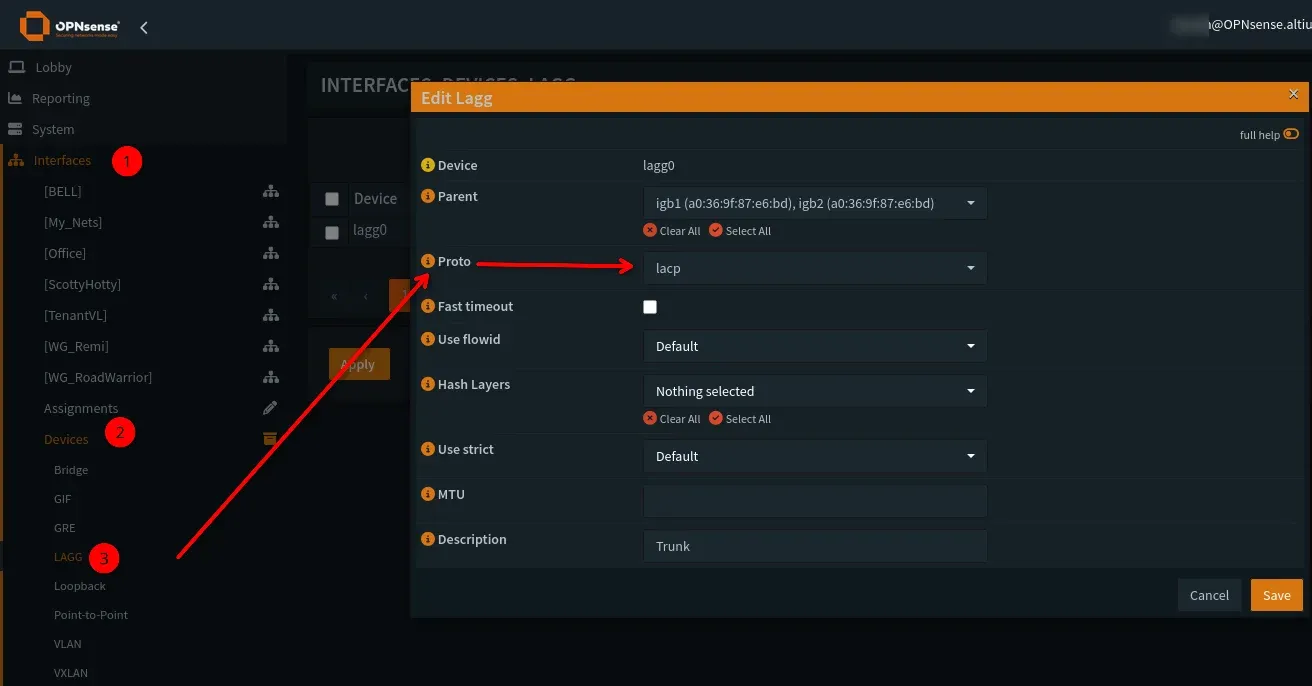
- Decide on your hash layer of choice. This is important and will have to be compatible with the switch you are uplinking too. If you're not sure, you can leave "nothing" and leave it completely to the switch.
If you will connect all your VLANs to your network via this method, expand this toggle and read it. If you will use separate interfaces off OPNsense, skip it!
🚨 CRITICAL WARNING: RISK OF LOCKOUT 🚨
This is the single most common place where users lock themselves out of their firewall.
Here is a detailed guide on how this works and the safe way to configure it. Read this section twice before you change any settings.
You are currently accessing your OPNsense GUI using your LAN interface (e.g., at 10.10.1.1). This traffic is on your default, untagged network (often called VLAN 1). The VLANs you just created (IOT, CAMERAS, etc.) send tagged traffic.
You are about to configure the same physical port on your managed switch to accept both your untagged LAN traffic AND the new tagged VLAN traffic.
If you configure the switch port incorrectly (e.g., you forget to allow the untagged VLAN 1 or set the wrong Native VLAN), the switch will stop passing your LAN traffic. You will be immediately disconnected and locked out of your OPNsense GUI.
Recovery: The only way to recover is to plug a computer directly into a different OPNsense port (if you have one) or connect via the console port (if your hardware has one) to revert the settings.
Totally valid if you have say, a quad (4) port intel NIC, to manage OPNsense from 1 (the default) and select igb1&2 to be members, and test uplinking to the switch util you have it working juuusst right!
What You've Accomplished Thus Far
What you've built is a classic "router-on-a-stick." Your single physical LAN port on OPNsense is now acting as a "trunk" that carries multiple networks.
- It sends untagged traffic for your main
LAN(VLAN 1). - It sends tagged traffic for
MANAGEMENT(VLAN 10),GUEST(VLAN 20),IOT(VLAN 30), etc.
Our goal is to configure the switch port on the other end of that cable to understand this "hybrid" setup.
You don't actually configure a "trunk port" in OPNsense. You already did the work:
- You created VLANs (Tag 10, 20, 30...) and set their Parent to your physical
LANinterface. - You assigned those VLANs to new interfaces (
MANAGEMENT,GUEST,IOT).
By doing this, you have told OPNsense to send tagged traffic for those VLANs out of the physical LAN port. The OPNsense side is complete. The work is now on your switch.
The Managed Switch Side (The Real Work)
Log in to your managed switch (UniFi, TP-Link Omada, Netgear, etc.). The terminology will vary, but the steps are the same.
- Navigate to your Switch's Port Settings: Find the list of ports on your switch.
- Identify the Trunk Port: Select the single physical port that your OPNsense
LANinterface is plugged into. - Edit the Port Profile/Configuration: You need to change this port's mode from a simple "Access" port to a "Trunk" port.
- Configure VLANs on the Port: This is the critical step.
- Native VLAN (or PVID / Untagged VLAN): Set this to your main LAN's VLAN ID. By default, this is
VLAN 1. This setting tells the switch: "Any untagged traffic that comes from this port (like your OPNsense GUI access) belongs to VLAN 1." This is the step that prevents you from being locked out. - Tagged VLANs (or Allowed / Trunked VLANs): Set this to allow all the tagged VLANs you created. You will need to add
10,20,30,40, and50to the "allowed" list for this port.
- Native VLAN (or PVID / Untagged VLAN): Set this to your main LAN's VLAN ID. By default, this is
- Save and Apply: Save the configuration on your switch.
Example: UniFi Switch Configuration
- Port Profile: You would edit the port and select a profile where:
- Native VLAN:
LAN (1) - Tagged VLANs:
MANAGEMENT (10),GUEST (20),IOT (30),CAMERAS (40),DMZ (50)
- Native VLAN:
Example: TP-Link Omada Switch Configuration
- Port Profile:
- Type:
All(orCustom) - Native Network:
LAN (1) - Tagged Networks: Check the boxes for
MANAGEMENT (10),GUEST (20),IOT (30),CAMERAS (40),DMZ (50)
- Type:
After applying the switch settings, your single "router-on-a-stick" connection is complete. Your (untagged) LAN traffic will continue to work, and your switch will now correctly direct tagged traffic for your other VLANs to and from the OPNsense firewall.
Intro to Packet Flow in OPNsense
Before we dive into alias & firewall rule creation, we will quickly cover how packets are analyzed and how the firewall "sees" them.
🧱 Example 1: WAN ➡️ LAN (Incoming Connection)
flowchart LR
    subgraph INTERNET["🌐 Internet (Untrusted)"]
        A["Remote Host (1.2.3.4)"]
    end

    subgraph OPNsense["🧱 OPNsense Firewall"]
        B["WAN Interface"]
        C["Packet Filter"]
        D["LAN Interface"]
    end

    subgraph LAN["🏠 Internal Network"]
        E["Home PC (192.168.7.10)"]
    end

    A -->|"Inbound packet to WAN"| B
    B -->|"WAN rules checked 🔍"| C
    C -->|"Allowed if passes (e.g. port forward + stateful rule)"| D
    D -->|"Forwarded to LAN"| E

    %% Blocklist example
    B -.->|"🧾 FireHOL Blocklist\n(Drops known bad IPs)"| C
🚀 Example 2: LAN ➡️ WAN (Outbound Connection)
flowchart LR
    subgraph LAN["🏠 Internal Network"]
        A["Home PC (192.168.7.10)"]
    end

    subgraph OPNsense["🧱 OPNsense Firewall"]
        B["LAN Interface"]
        C["Packet Filter"]
        D["WAN Interface (NAT out)"]
    end

    subgraph INTERNET["🌐 Internet (Untrusted)"]
        E["Remote Server (1.2.3.4)"]
    end

    A -->|"Outbound packet (Inbound to Opn)\n(from LAN host)"| B
    B -->|"LAN rules checked 🔍"| C
    C -->|"Pass if allowed (default allow LAN→WAN)"| D
    D -->|"Translated via NAT"| E

    %% Blocklist example
    D -.->|"🧾 FireHOL Blocklist\n(Drops bad destinations)"| E
You can read about the Direction right here, from the official docs:
Why "Blocked by Default" Isn't the Whole Story🤯
When you create VLAN_10, VLAN_20, and VLAN_30 for example, OPNsense creates the interfaces but adds no Pass rules to them. Because the default policy is to deny all, this means:
- Nothing from the WAN can get in to those VLANs.
- Nothing from
VLAN_10can get out to anywhere (not the internet, notVLAN_20).
So, yes, all inter-VLAN traffic is blocked by default. But this is because the new VLANs can't send any traffic at all.
The "Internet-Only" VLAN Rule
Let's say you want VLAN_10 to be your "Guest" network. You want devices on it to access the internet, but you never want them to access VLAN_20 (Your LAN) or VLAN_30 (Your Servers).
The "Lazy" Way (And Less Secure): You could add a single rule to the VLAN_10 interface:
- Action:
Pass - Source:
VLAN_10 net - Destination:
any<- Danger!
This rule allows VLAN_10 to access the internet, but it also allows VLAN_10 to send traffic to VLAN_20 and VLAN_30. Remember, the Destination was set to ANY and the firewall accepts that. The traffic would still be blocked (for now) by the default deny on the inbound side of VLAN_20 and VLAN_30. But if you ever add a rule to VLAN_20 to allow, say, a web server to be accessed, your VLAN_10 guests could suddenly access it. This is an "implicit deny" and relies on other rules being perfect.
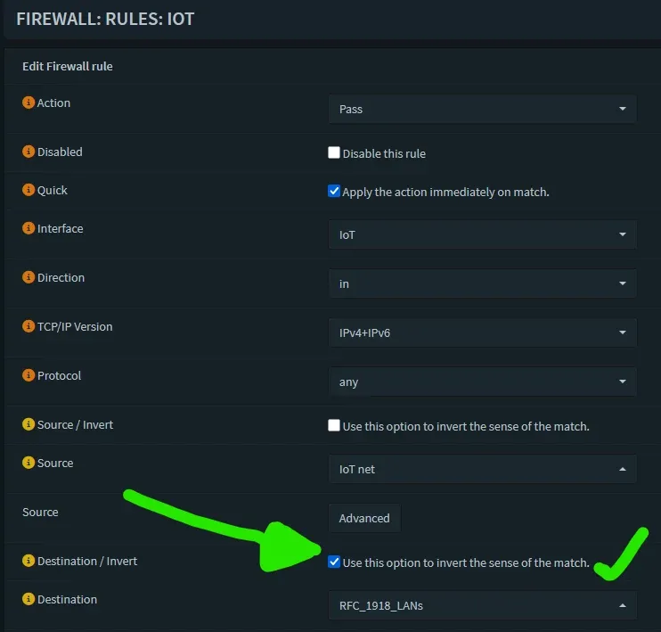
The "Correct" Way (Your Inversed Rule):v On the VLAN_10 interface, you create this rule:
- Action:
Pass - Interface:
VLAN_10 - Source:
VLAN_10 net - Destination:
!RFC1918 - Destination / Invert
Checked✅ - Description:
Allow Internet, Block Inter-VLAN
This rule is brilliant for two reasons:
- It does what you want: It
Passestraffic where the destination is NOT (!) an RFC1918 private address. Public internet IPs are not RFC1918, so that traffic is allowed. You get internet from that VLAN. - It does what you don't want (and this is the key): When a device on
VLAN_10tries to reachVLAN_20(e.g.,192.168.20.1), that destination is an RFC1918 address. This rule will not match. The firewall then continues to the next rule, finds nothing, and hits the default deny rule. Each VLAN is secure by default.
Step 5: Building the Moat with Automated IP Blocklists (Aliases)
Now that our networks exist, we define what they are and who the bad guys are.
Step 5.1: Create the RFC1918 Alias (The "Private" List)
This alias allows us to easily define "Internal Networks" in a single rule. This implements a "default-deny" stance between your internal networks (VLANs) and ensures only devices using valid private IP addresses from your network can initiate connections to the internet. This is incredibly efficient, effective and easy to implement! This will ensure each of your newly created VLANs is kept out of each other and secure. Your IoT devices even if they were breached, won't allow an attacker to now instantly pivot into your home LAN network!
- Navigate to Firewall -> Aliases.
- Click + (Add).
- Name:
RFC1918_Networks - Type: Network(s)
- Content:
10.0.0.0/8172.16.0.0/12192.168.0.0/16
- Description: "All RFC1918 Private Network Ranges".
- Save.
Step 5.2: Create Dynamic Blocklist Aliases
Navigate to Firewall -> Aliases. Click the + (Add) button for each one.
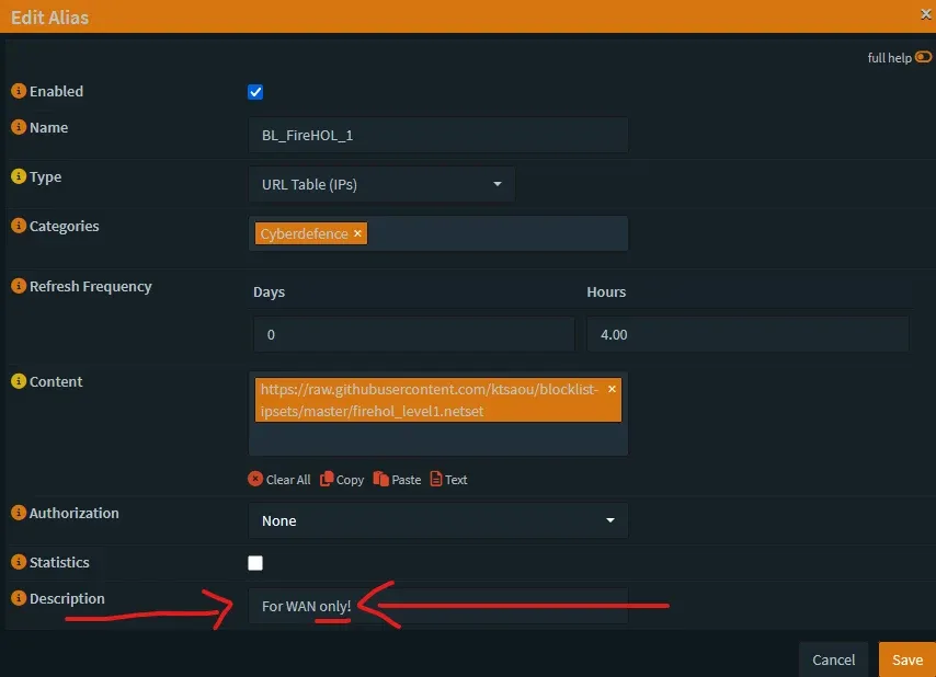
- FireHOL Level 1 (WAN Inbound ONLY):
- Name:
Blocklist_FireHOL_L1 - Type:
URL Table (IPs) - Refresh Freq.:
1(Days) - Content:
https://iplists.firehol.org/files/firehol_level1.netset - Description: "FireHOL L1 - Use for WAN INBOUND only. Contains bogons/private IPs."
- Save.
- Name:
- FireHOL Level 2 (Inbound & Outbound):
- Name:
Blocklist_FireHOL_L2 - Type:
URL Table (IPs) - Refresh Freq.:
1(Days) - Content:
https://iplists.firehol.org/files/firehol_level2.netset - Description: "FireHOL L2 - Safe for WAN IN and LAN OUT."
- Save.
- Name:
- FireHOL Level 3 (Inbound & Outbound):
- Name:
Blocklist_FireHOL_L3 - Type:
URL Table (IPs) - Refresh Freq.:
1(Days) - Content:
https://iplists.firehol.org/files/firehol_level3.netset - Description: "FireHOL L3 - Safe for WAN IN and LAN OUT."
- Save.
- Name:
- Spamhaus+Others DROP (WAN & LAN):
- Name:
Blocklist_Spamhaus or BL_KnownBaddies - Type:
URL Table (IPs) - Refresh Freq.:
4(Hours, do it at least once every 24hrs) - Content:
https://www.spamhaus.org/drop/drop.txt- OPTIONAL - I have a pile more as well that I added, as shown below.
- Description: "Spamhaus DROP List - Safe for WAN IN and LAN IN."
- Save.
- Name:
https://www.spamhaus.org/drop/drop.txt
http://cinsscore.com/list/ci-badguys.txt
http://lists.blocklist.de/lists/all.txt
https://feodotracker.abuse.ch/downloads/ipblocklist_aggressive.txt
https://www.binarydefense.com/banlist.txt
https://raw.githubusercontent.com/stamparm/ipsum/master/ipsum.txt
http://blocklist.greensnow.co/greensnow.txt
https://www.stopforumspam.com/downloads/toxic_ip_cidr.txt
https://reputation.alienvault.com/reputation.generic
My list of baddies
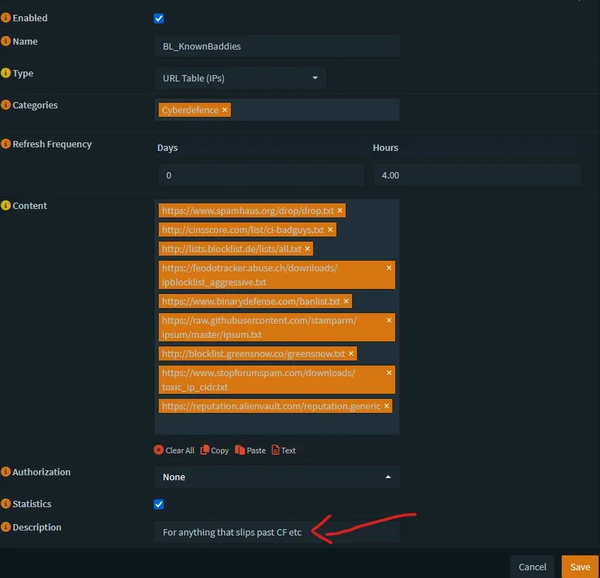
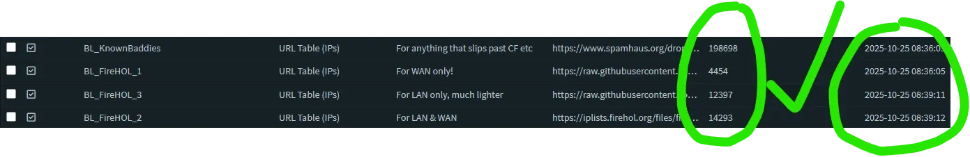
At the end you should have something like this:
Step 5: 🔥The Firewall Engine - Mastering the New Unified Rules GUI🔒
This is where we bring it all together. We will use the "Invert Match" logic for a clean, fail-safe ruleset. If a setting is not explicitly specified below, that means leave it to "default". Example, Direction: In, is usually the default when creating a new rule.
Key Terminology Change: > Port Forwarding is now officially called Destination NAT.
Policy Routing is now integrated directly into the standard rule editor rather than hidden in advanced settings.
The "New" Rules Interface: Navigate to Firewall -> Rules (New). You’ll notice a cleaner, grid-based view. This isn't just a coat of paint; it’s an API-driven system that allows for much faster rule processing and easier searching.
You need to repeat this process on the rules tab for each of your internal interfaces (LAN,IOT,CAMERAS, etc.).
We'll use LAN as the example. I don't recommend using floating for this as you want to be able to change them individually and be granular, at first.
Step 6.1: LAN Rules (Trusted)
Go to Firewall -> Rules[new] -> Top drop down to your LAN.
- Block Bad Guys (Outbound):
- Action: Block | Source: LAN net | Destination:
Blocklist_Spamhausand any other BL you created as per above, except for theFireHol Level 1! That one only gets used on WAN, not LAN.- Ensure you place this at the very top of your rules order!
- Action: Block | Source: LAN net | Destination:
- Allow Inter-VLAN Access (Specific Holes):
- If you need LAN to reach IOT, add that HERE, above the internet rule.
- Action: Pass | Source: LAN net | Destination: IOT net
- Allow Internet (Default Deny Internal to internal):
- Action: Pass
- Source: LAN net
- Destination:
RFC1918_Networks - Invert Match: CHECK THIS BOX (!).
- Note: In the new GUI, the "Invert" checkbox is more clearly labelled. This rule tells OPNsense: "If the traffic is NOT headed for my private internal networks, let it go to the internet."
- Description: "Allow LAN to Internet (Block Inter-VLAN)"
- Note: This single rule allows you to access Google, but blocks you from accidentally accessing the DMZ or Guest network unless you explicitly allowed it in rule #2.
Step 6.2: GUEST / IOT / DMZ Rules (Untrusted - Internet Only)
Go to Firewall -> Rules[new] -> GUEST. We only need ONE rule here!
- Allow Internet (Block Internal):
- Action: Pass
- Direction: IN
- Source: GUEST net
- Destination:
RFC1918_Networks - Invert Match: CHECK THIS BOX (!).
- Description: "Allow GUEST to Internet (Block Inter-VLAN)"
You can leave IPV6 out if not using or enabling it.
Repeat this exact rule for the IOT and DMZ interfaces. At the end you'll have created a rule like this for each VLAN you have created looking like this:
Step 6.3: CAMERAS Rule (Isolated - No Internet)
Go to Firewall -> Rules -> CAMERAS.
- Block Everything:
- Action: Block
- Source: CAMERAS net
- Destination: any
- Description: "Block all traffic from CAMERAS"
- If you want to allow them out to the internet but NOT to any of your LANs, make the rule similar to step 5.2!
Step 6.4: OPTIONAL - Advanced INBOUND LAN Blocking (Using Blocklists)
This rule is explicitly defined so you're extra careful. This prevents things in your network from 'dialing home'. Scenario, your kid invites a friend over after school and they bring their tablet or laptop to play with yours. Cool, you hook them up and voila - they have internet AND - their device is infected with malware, dialed home to a botnet C & C server and is downloading a crypto-locker worm to encrypt all the devices it can find on your network! 🤯 You won't have joined them to your internal private LAN anyway right? Because you made a GUEST vlan right?
- The INBOUND Block Rule (LAN Interface):
- Go to Firewall -> Rules -> LAN.
- Click
+(Add). - Action:
Block - Quick: Check this box.
- Interface:
LAN - Direction:
in - Protocol:
any - Source:
any - Destination: Click in the field, start typing, and select each of these aliases one by one:
- ⚠️DO NOT add FireHol1 here‼️😨 Notice it's MISSING from the list below (on purpose!)
Blocklist_FireHOL_L2Blocklist_FireHOL_L3Blocklist_Spamhaus/BL_KnownBaddies- Log: Check this box.
- Description: "Block internal clients from phoning home to bad IPs"
- Save.
- Apply Changes & Re-order: A new rule on the LAN interface may require you to move it. On the
LANrules tab, this newBlockrule must be ABOVE the default "Allow LAN to !RFC_1918" rule. Use the arrow buttons to re-order your rules so it looks like this:Block internal clients from phoning home...Default allow LAN to !RFC_1918_LANs rule
Every time you add a new blocklist or deny traffic rule, you'll want to keep adding it above your allow rules for the blocks to function.
Additional Warning: This might be overkill for you and may require tweaks. When I first started using it, it was blocking Github entirely. This is because a lot of attacks / bots / script kiddies make web calls to Github and 'abuse' their system, so IP addressing from them gets placed on 'naughty' lists frequently.
I temp disabled the rule while I did my Github work.
Step 6.5: WAN Rules (The Shield)
Go to Firewall -> Rules -> WAN. 🏹You want these rules at the TOP of your WAN ruleset and it would look something like:

I kept mine in separate rules so I could log them separately but you can totally put them in one.
- If you publicly expose services with a reverse proxy, to say, host your own blog, maybe jellyseerr/overseerr, or anything you opened to the WAN and;
- To enhance visibility & insight into what is actually hitting you.
Default 'deny' rule will show you, but you won't know at a glance, if this is a known bad actor, a bot, or just random internet traffic otherwise. By making a clearly defined list & rule, you see when it's actually malicious traffic or not.
A critical warning: IP blocklists are not all the same. Using the wrong list on the wrong rule can block your entire network. We will use a safe, layered approach
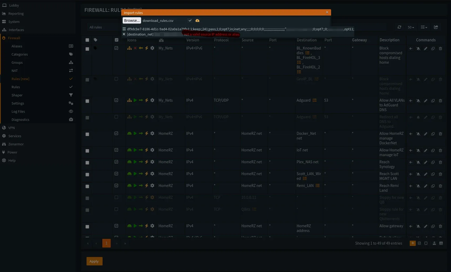
- Block Known Bad IPs:
- Action: Block
- Quick: Checked.
- Source:
Blocklist_FireHOL_L1,Blocklist_FireHOL_L2,Blocklist_FireHOL_L3,Blocklist_Spamhaus,all other Blocklists - Direction:
in - Destination: any
- Description: "Block all known-bad IPs & bogons on WAN IN"
- Log: Check this box.
What you should have now is a rule containing the block lists for everything on WAN, and all lists LESS FireHol1 on LAN.
TEST. 🧩Browse the internet, make sure things are functional. Often the trip up happens by incorrectly applying the BL's in the proper order, most importantly, FireHol level 1 blocking on WAN INBOUND ONLY! If you have issues, disable blocks on outbound and test again, troubleshoot from there.
If all goes well, you should see some good info like this (I removed Destinations to protect my WAN IP):
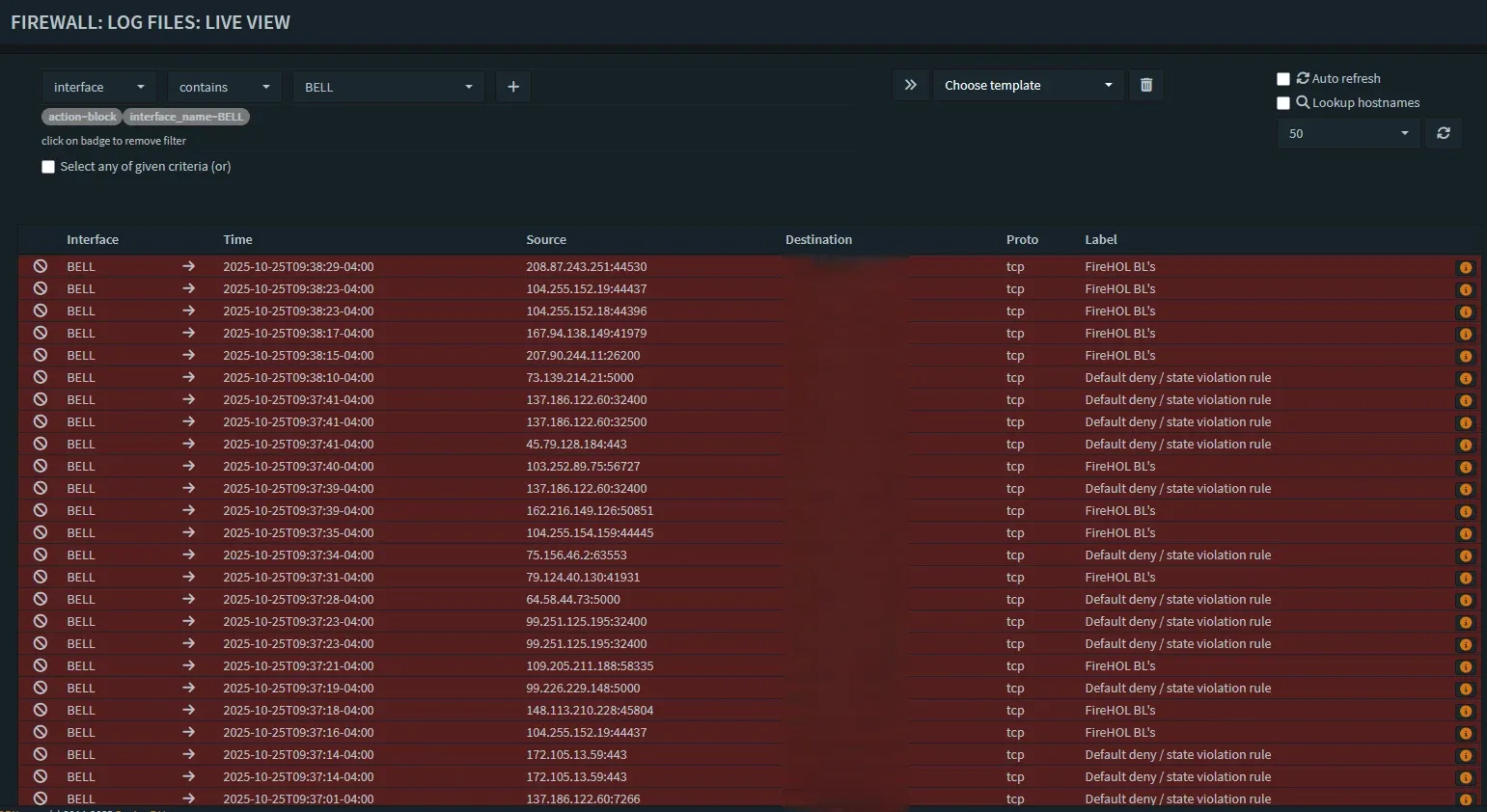
Victory in real-time! Blocks started showing up immediately!
Step 6.6: Common "Poke a Hole" Rules (Inter-VLAN)
Now that we have established a "Default Deny" posture between our VLANs, you will inevitably find something that breaks. You might need your Plex server to talk to your Apple TV, or your Home Assistant instance to talk to a smart plug.
Note on Smart Home / IoT Control Across VLANs
You might wonder how controlling smart devices (like Meross lights or Google Home devices) works if your phone is on one VLAN (e.g., HomeRZ) and the IoT devices are on another (IOT) now that we've blocked inter-VLAN traffic by default. There are two main ways this happens:
- Cloud-Based Control (Usually Works Automatically):
- Most major smart home platforms (Google Home, Amazon Alexa, Meross Cloud, Tuya Smart Life, etc.) primarily rely on the cloud.
- When you use the app on your phone (on
HomeRZ), it sends the command up to the manufacturer's cloud service (via your allowed internet connection). - The cloud service then sends the command back down through your firewall's WAN interface to the specific IoT device (on the
IOTVLAN, which typically is allowed to access the internet to reach the cloud service). This is ok, if you're ok relying on / using their services. - Result: Because the command path doesn't directly cross from
HomeRZ->IOTinternally, your default-deny inter-VLAN block rule doesn't usually interfere. This method often continues working without specific rules. ✅
- Local Network Control (Requires Specific Rules):
- Some apps or features rely on discovering and controlling devices directly on the local network using protocols like mDNS (Bonjour/Avahi) for discovery (often UDP port 5353) or SSDP (UPnP discovery) (often UDP port 1900), plus specific TCP/UDP ports for device control.
- Result: Your new default-deny rule will block this direct
HomeRZ->IOTtraffic. 🚫 - Solution: If local control fails, you'll need to identify the specific ports and protocols the device/app uses (check manufacturer documentation or use the firewall logs at Firewall -> Log Files -> Live View to see blocked attempts) and create specific
Passrules on the source interface (HomeRZin this example) allowing traffic from your phone/controller to the specific IoT device IP(s) or the wholeIOT neton those required ports. Setting up mDNS/SSDP repeaters (available as plugins likeos-udpbroadcastrelayoros-mdns-repeaterin OPNsense) can also help with discovery across VLANs, but you'll still likely needPassrules for the actual control traffic.
In most common scenarios, cloud control keeps things working, but be prepared to add specific Pass rules if you rely on local discovery and control features for certain devices. Always check those firewall logs first!🪵
Here are the three most common "Allow" rules you will create. Crucially, these must be placed at the TOP of your rule list, above the !RFC1918 Internet rule!
Scenario A: The "God Mode" Rule (1 IP to Whole Subnet) Use Case: You want your personal Desktop PC to be able to access ANY device on the IoT network (to configure them).
- Action: Pass
- Interface: LAN
- Source: Single Host or Network ->
10.10.1.50(Your PC IP) - Destination: IOT net
- Description: "Allow Admin PC to access all IOT devices"
Scenario B: The "Server to Server" Rule (1 IP to 1 IP) Use Case: Your Plex Server (on LAN) needs to talk to your NAS (on MANAGEMENT) for file storage.
- Action: Pass
- Interface: LAN
- Source: Single Host or Network ->
10.10.1.10(Plex IP) - Destination: Single Host or Network ->
10.10.10.5(NAS IP) - Description: "Allow Plex to access NAS"
Scenario C: The "Surgical" Rule (1 IP to 1 IP on Specific Port) Use Case: Your Home Assistant (on LAN) needs to control a specific Smart Plug (on IoT) via MQTT (Port 1883), but shouldn't access anything else.
- Action: Pass
- Interface: LAN
- Source: Single Host or Network ->
10.10.1.20(Home Assistant IP) - Destination: Single Host or Network ->
10.10.30.55(Smart Plug IP) - Destination Port Range:
1883(from) to1883(to) - Description: "Allow HA to Smart Plug on MQTT"
Step 6.7: Removing the Training Wheels (The Default LAN Rule)
When you first installed OPNsense, it created a rule on your LAN interface called "Default Allow LAN to any rule".
You must disable this rule.
Why? If you leave this rule enabled at the bottom of your list, your !RFC1918 rule will work fine for the internet, but any traffic destined for your other VLANs (which is RFC1918 traffic) will simply skip that rule, fall down to the "Default Allow," and be allowed to pass. This breaks your segmentation!
- Navigate to Firewall -> Rules -> LAN.
- Locate the rule at the bottom named "Default Allow LAN to any rule" (It usually has a lock icon next to it indicating it was auto-generated, or just look for the generic pass rule).
- Do not delete it yet. Just click the green "Play" icon (✅) to toggle it to a gray "Disable" icon (❌).
- Apply Changes.
- Test: Try to ping a device on your IOT VLAN from your LAN. It should fail. Try to browse the internet. It should work (thanks to your Step 5.1 rule).
- Once you are confident everything is working, you can leave it disabled or delete it entirely.
Note on the Anti-Lockout Rule: You might see a rule at the very, very top called "Anti-Lockout Rule". Leave this alone. This is a special system failsafe that ensures you can always access the OPNsense GUI on the LAN port, even if you mess up your other rules.
Step 6.9: Floating Rules?
I would wait to play with floating rules until you're a bit more comfortable with OPN. Basically, floating rules apply across interfaces, or alias groups of interfaces. An example would be making an alias of your internal LANs and making a rule allowing all of those LANs to reach your Adguard/PiHole server for DNS.
You can achieve this across all your interfaces or an interface group as a floating rule, if you like, but uncheck "quick match" if you do. It is very important that you uncheck "Quick". This means that your floating rules allow your VLAN-to-WAN rules to take processing/order precedence and will be processed after all your other "quick" rules, by default.
In simple terms: This way if you have other rules defined on your specific interfaces, those will process first.
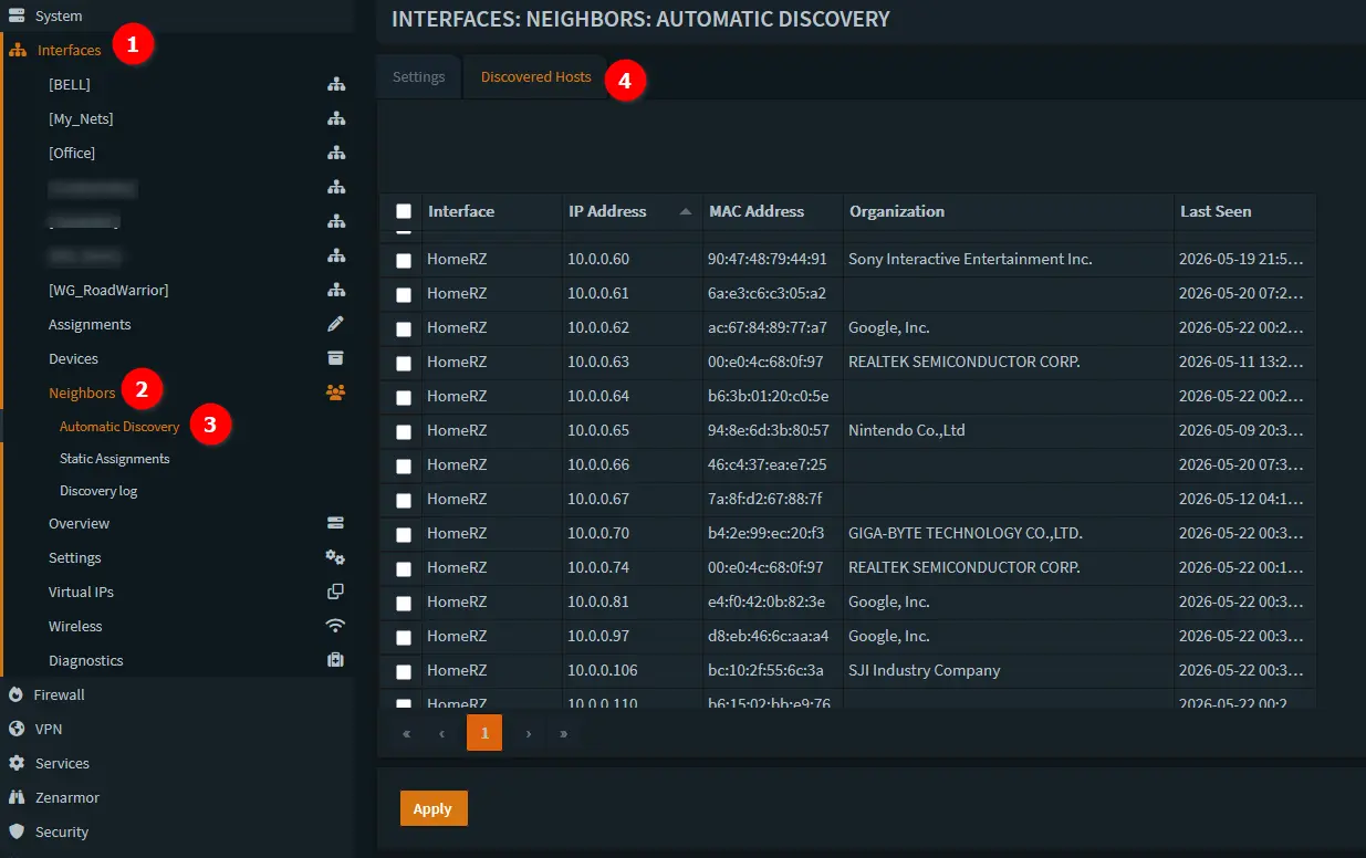
Step 7: Visibility with Hostwatch & The New Dashboard
One of my favourite additions in the 26.1 release is Hostwatch (Interfaces -> Neighbors -> Automatic Discovery). This service sits silently in the background and maps out every device that touches your network!
- Why it matters: It populates your New Dashboard widgets with real device names instead of just MAC addresses, giving you instant situational awareness if a new "Smart Bulb" suddenly starts talking to a server in Eastern Europe.
Result & Conclusion🎯:
Traffic between your VLANs is now blocked by default by the final rule on each interface. You must create specific Pass rules above it to allow necessary inter-VLAN communication.
- Only traffic originating from devices within a specific VLAN's subnet (
Source: <VLAN> net) is allowed to go out to the internet (Destination: not RFC1918_Networks). - This is a massive leap forward in your security posture!
- Don't forget to configure your managed switch with those VLANs now! There's a small guide above in the Section 3, Step 3.4: "Router on a Stick" if you missed, it, expand the warning toggle.
Head on over to Part 2 when you're ready and don't forget to check the OPNsense change logs before you patch 😉
💬 Report Success - Hell Yeah I Set this up!🎉 Lab Task Complete!
Did you survive the configuration? Let the world know!

Or take a bit of a deeper dive into foundational networking and VLANS. 👇

Member discussion